

There is more than one type of fin that can be used in gas-to-fluid heat exchangers, and each of these fin types has its own distinct design and method of attachment. In addition, there is more than one type of gas-to-fluid heat exchanger. The selection of the type of extruded fin tube that is best suited for a specific environment is contingent on the setting in which it will be used. This is due to the fact that every type of fin possesses both benefits and drawbacks in specific applications.
The Fins of the Plate
In the Plate Fin design, holes for the tubes are pressed into relatively thin sheets of metal. After inserting these tubes into the holes, the tubes are then expanded to their full length. This very effective type of extruded fin tube offers a very large surface area, which contributes to the more even distribution of heat throughout the system. It is possible for the fins to have a waffled or rippled pattern, which will result in increased efficiency. It is possible to use fins of varying thicknesses, with thinner fins being used in situations in which cost is the primary consideration and cleanability is not a concern, and thicker fins being used in situations in which ruggedness and cleanability are the primary concerns, respectively.
That Had a Tension-Wound in Its Fin
The shape that the tension wound takes. After being tightly wound around the tube, the fins are held together by being stapled or welded at the ends. This is how the fin is held together. Solder coating is another option for increasing the corrosion resistance of tension-wound fins. This coating can be applied using solder. When utilizing a tension wound fin, it is recommended that both the fins and the tubes be made of the same material.
a footed fin in the shape of an L
The distinctive appearance of the 'L' Footed Fin is due to the fact that it has a lip at the base of the fin that is tension wound around the tube. As a result, there will be less of an exposed joint at the base of the fin, while at the same time there will be a greater increase in the contact area and the heat transfer contact area between the tube and the fin.
An 'L'-Shaped Fin That Overlaps Itself
The Overlapped 'L' fin design is characterized by having a number of features, one of which is interlocking fins that are wound together to prevent movement and separation. This design is effective for use in situations in which there is a risk of corrosion. This is due to the fact that the fin protects the entirety of the tube.
The Fin Is Set Within the Body
The extruded fin tube is first inserted and then welded into a helical groove that has been cut into the tube in the configuration that is known as the Embedded Fin design. They have a high level of durability and are able to withstand higher temperatures without breaking down. Applications that involve high temperatures or thermal cycling are ideal candidates for incorporating embedded fins. Additionally, applications that are ideal candidates include those in which the finside will be subjected to frequent cleaning.
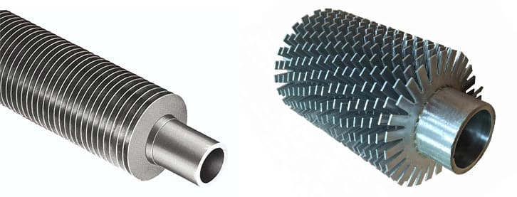
Fin that was ExtrudedComposed of Just One Type of Metal
Extruded Fins, also known as Integral Fins, are produced by feeding thick-walled tubes into a press that cold-works the fin until it is extruded from the tube. This process is also known as the Extruded Fin method. The cold working process makes the fins easier to clean and more durable. Additionally, the fins become more durable as a result of the process. Because there is no bi-metal joint that is exposed on the gas side, the potential for galvanic corrosion has been eliminated. The mono-metal fin shines the brightest when used in applications that involve low pressure.
Bi-Metal Extruded Fin (also known as Integral Bi-Metal Extruded Fin)
The production of extruded fins, which are also referred to as integral fins, begins with the insertion of a liner tube into a thick-walled tube, which is then followed by the passage of this assembly through a press that extrudes the extruded fin tube from the thick-walled tube using a cold working technique. Extruded fins are also known as integral fins. During the process of creating a mechanical bond between the outer (finned) tube and the liner tube, the outer tube is pressed into a pattern that looks like fins. This allows for a more secure connection between the two tubes. Because the fins are made from a single piece of material, there is no exposed bi-metal joint at the base of the fin. Because only a small portion of the liner tube is exposed to the gas side, it is possible to select the liner tube that will work best with the fluids on the tubeside. This is made possible by the fact that only a small portion of the liner tube is exposed to the gas side.
Brazed aluminum fins (or plate and bar fins) have headers and face bars attached to them, and the fins themselves are laid between two braze sheets made of aluminum. The headers and face bars are attached to the fins.
A unified core is created by placing the assembled unit in a vacuum braze furnace and meticulously controlling the amount of time and temperature for the duration of the process. This results in the core being melted together into a single mass. It is common practice to install an internal fin on the interior of a device in order to improve the way heat is transferred.